基于端口位置的实例化
题目描述
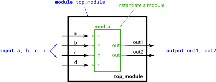
创建一verilog电路,实现对模块mod_a基于端口位置的实例化,如下图所示:
其中mod_a模块的代码提供为:
1
2
3
4
5
6
7
8
module mod_a(output out1, out2,input in1,in2,in3,in4);assign out1 = in1 & in2 & in3 & in4;assign out2 = in1 | in2 | in3 | in4; endmodule
Hint:
实例化名称可以与模块名称相同
实例化模块时,需要注意端口信号的位宽相匹配,本例中都是1bit,所以不存在问题
输入格式
4个1bit信号a, b, c, d
输出格式
经由模块mod_a输出的信号out1, out2
代码和解析
如题目所说,像调用函数一样依次传“参数”即可,注意位置要一一对应。
1
2
3
4
5
6
7
8
9
10
11
12
13
14
15
16
17
18
19
20
21
module mod_a(output out1, out2,input in1,in2,in3,in4);assign out1 = in1 & in2 & in3 & in4; assign out2 = in1 | in2 | in3 | in4; endmodule module top_module( input a, input b, input c,input d,output out1,output out2endmodule
基于端口名称的实例化
题目描述
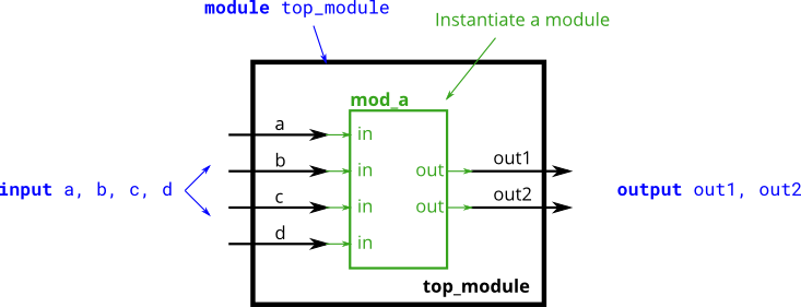
创建一 verilog 电路,实现对模块 mod_a 基于端口名称的实例化,如下图所示:
其中mod_a模块的代码为:
1
2
3
4
5
6
7
8
9
10
11
module mod_a (output out1,output out2,input in1,input in2,input in3,input in4assign out1 = in1 & in2 & in3 & in4; assign out2 = in1 | in2 | in3 | in4; endmodule
输入格式
输入信号 a, b, c, d,位宽 1bit。
输出格式
输出信号 out1, out2,位宽 1bit。
代码和解析
除了像C语言一样按顺序传参数以外,Verilog还可以进行基于端口名称的实例化,如这道题所示。
1
2
3
4
5
6
7
8
9
10
11
12
13
14
15
16
17
18
19
20
21
22
23
24
25
26
27
28
29
module mod_a (output out1 ,output out2 ,input in1 ,input in2 ,input in3 ,input in4assign out1 = in1 & in2 & in3 & in4; assign out2 = in1 | in2 | in3 | in4; endmodule module top_module ( input a ,input b ,input c ,input d ,output out1,output out2.out1 (out1),.out2 (out2),.in1 (a),.in2 (b),.in3 (c),.in4 (d));endmodule
多个模块的例化
题目描述
对于给定模块my_dff,包含两个输入信号和一个输出信号(D触发器模块),其代码如下:
1
2
3
4
module my_dff(input clk,input d,output reg q);always @(posedge clk)endmodule
请创建一verilog模块,在该模块中将my_dff模块例化3次,并串行连接,使其构成一个长度为3的移位寄存器,其中3个模块公用一个clk信号,如下图所示:
为实现电路功能,用户需要在顶层模块定义一些内部信号,从而能够将3个例化的模块进行连接。
输入格式
2个 1bit 位宽信号 clk、d
输出格式
1个 1bit 位宽信号 q
代码和解析
只需要对于图里面的两个粗箭头定义两个wire型中间信号即可。
1
2
3
4
5
6
7
8
9
10
11
module my_dff(input clk,input d,output reg q);always @(posedge clk)endmodule module top_module ( input clk, input d, output q );wire w1,w2;.clk (clk),.d (d),.q (w1));.clk (clk),.d (w1),.q (w2));.clk (clk),.d (w2),.q (q));endmodule
模块与向量信号
题目描述
对于给定模块 my_dff8,其代码如下所示:
1
2
3
4
5
6
7
8
module my_dff8(input clk,input [7 :0 ] d,output reg [7 :0 ] qalways @(posedge clk)endmodule
试创建一 Verilog 模块,对 my_dff8 模块例化 3 次,并串行连接,构成一个 8bit 位宽长度为 3 的移位寄存器,同时可以通过选择信号选择输出结果,如下图所示:
输入格式
8bit 的任意有效输入
输出格式
根据 sel 信号,选择一个模块或者原输入作为输出信号
代码和解析
比特矢量是可以作为一个信号直接参与模块例化的,这也是我之前说要把比特矢量看成一个“数”的原因之一。
1
2
3
4
5
6
7
8
9
10
11
12
13
14
15
16
17
18
19
20
21
22
23
24
25
26
27
28
29
30
31
module my_dff8(input clk,input [7 :0 ] d,output reg [7 :0 ] qalways @(posedge clk)endmodule module top_module(input clk,input [7 :0 ] d,input [1 :0 ] sel,output reg [7 :0 ] qwire [7 :0 ] w1,w2,w3;.clk (clk),.d (d),.q (w1));.clk (clk),.d (w1),.q (w2));.clk (clk),.d (w2),.q (w3));always @(*) begin case (sel)0 :q=d;1 :q=w1;2 :q=w2;3 :q=w3;default : q=8'b00000000 ;endcase end endmodule
这里用到了always块,是以前没有用到过的,但是我后面几个题的时候再来讲解。
加法器
对于给定的16bit加法器电路,其代码如下:
1
2
3
module add16 ( input [15 :0 ] a, input [15 :0 ] b, input cin, output [15 :0 ] sum, output cout );assign {cout,sum} = a + b + cin;endmodule
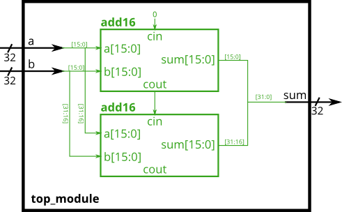
试创建一verilog模块,在该模块中实例化两个16bit的加法器,并进行适当的连接,最终构成一个32bit的加法器,该加法器输入进位位为0,如下图所示:
输入格式
32'b0 32'b0
输出格式
32'b0
代码和解析
这个题只需要读懂逻辑,然后照着图实现就可以了。这是一个典型的链接两个加法器的题,对于一个加法器(全加器),一般有三个输入:a,b是两个加数,cin是用来记录上一步有没有进位的值。输出一般有两个:sum是结果,cout是用来记录这个加法器有没有产生进位的值。
1
2
3
4
5
6
7
8
9
10
11
12
13
14
15
16
module add16 ( input [15 :0 ] a, input [15 :0 ] b, input cin, output [15 :0 ] sum, output cout );assign {cout,sum} = a + b + cin;endmodule module top_module(input [31 :0 ] a,input [31 :0 ] b,output [31 :0 ] sumwire [15 :0 ] sum1,sum2;wire w1,w2;.a (a[15 :0 ]),.b (b[15 :0 ]),.cin (0 ),.sum (sum1),.cout (w1));.a (a[31 :16 ]),.b (b[31 :16 ]),.cin (w1),.sum (sum2),.cout (w2));assign sum={sum2,sum1};endmodule
多层次例化加法器
题目描述
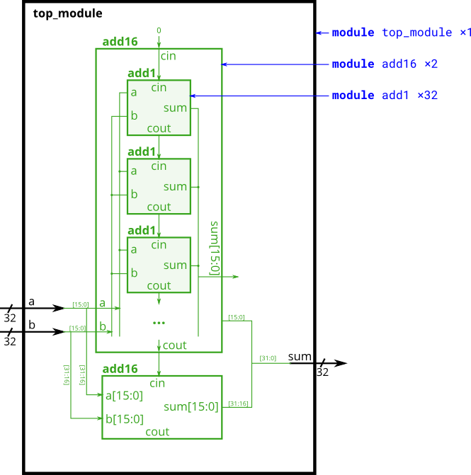
在此练习中,用户需要创建一个包含两层调用的电路,在顶层模块中,实例化两个16bit位宽的加法器add16,而add16模块又是通过例化16个1bit全加器实现的,如下图所示:
在本设计中,一共涉及到3个模块,分别是:顶层模块、add16模块、add1模块,其中add16模块源代码如下:
1
2
3
4
5
6
7
8
9
10
11
12
13
14
15
16
17
18
19
20
module add16 ( input [15 :0 ] a, input [15 :0 ] b, input cin, output [15 :0 ] sum, output cout);wire c1,c2,c3,c4,c5,c6,c7,c8,c9,c10,c11,c12,c13,c14,c15;.a (a[0 ]),.b (b[0 ]),.cin (cin),.sum (sum[0 ]),.cout (c1));.a (a[1 ]),.b (b[1 ]),.cin (c1),.sum (sum[1 ]),.cout (c2));.a (a[2 ]),.b (b[2 ]),.cin (c2),.sum (sum[2 ]),.cout (c3));.a (a[3 ]),.b (b[3 ]),.cin (c3),.sum (sum[3 ]),.cout (c4));.a (a[4 ]),.b (b[4 ]),.cin (c4),.sum (sum[4 ]),.cout (c5));.a (a[5 ]),.b (b[5 ]),.cin (c5),.sum (sum[5 ]),.cout (c6));.a (a[6 ]),.b (b[6 ]),.cin (c6),.sum (sum[6 ]),.cout (c7));.a (a[7 ]),.b (b[7 ]),.cin (c7),.sum (sum[7 ]),.cout (c8));.a (a[8 ]),.b (b[8 ]),.cin (c8),.sum (sum[8 ]),.cout (c9));.a (a[9 ]),.b (b[9 ]),.cin (c9),.sum (sum[9 ]),.cout (c10));.a (a[10 ]),.b (b[10 ]),.cin (c10),.sum (sum[10 ]),.cout (c11));.a (a[11 ]),.b (b[11 ]),.cin (c11),.sum (sum[11 ]),.cout (c12));.a (a[12 ]),.b (b[12 ]),.cin (c12),.sum (sum[12 ]),.cout (c13));.a (a[13 ]),.b (b[13 ]),.cin (c13),.sum (sum[13 ]),.cout (c14));.a (a[14 ]),.b (b[14 ]),.cin (c14),.sum (sum[14 ]),.cout (c15));.a (a[15 ]),.b (b[15 ]),.cin (c15),.sum (sum[15 ]),.cout (cout));endmodule
现在,你需要完成顶层模块和add1模块的verilog代码。
输入格式
两个32位宽的加数a,b
输出格式
32位宽的和sum
代码和解析
首先,第一部分是实现一位全加器add1,有两种实现方式。第一种是写出真值表,画出卡诺图并化简成逻辑表达式:
1
2
3
4
5
6
7
8
9
10
module add1 ( input a, input b, input cin, output sum, output cout );wire w1,a1,a2,a3;assign w1 = a ^ b;assign sum = w1 ^ cin;assign a1 = a & b;assign a2 = a & cin;assign a3 = b & cin;assign cout = a1 | a2 | a3;endmodule
第二种是基于行为建模,直接写出结果即可:
1
2
3
module add1 ( input a, input b, input cin, output sum, output cout );assign {cout,sum}=a+b+cin;endmodule
然后,第二部分就是top_module,这个没有什么新意,照着图写就行。
1
2
3
4
5
6
7
8
9
10
11
12
13
14
15
16
17
18
19
20
21
22
23
24
25
26
27
module top_module (input [31 :0 ] a,input [31 :0 ] b,output [31 :0 ] sum);wire w1,w2;wire [15 :0 ] sum1,sum2;.a (a[15 :0 ]),.b (b[15 :0 ]),.cin (0 ),.sum (sum1),.cout (w1).a (a[32 :16 ]),.b (b[32 :16 ]),.cin (w1),.sum (sum2),.cout (w2)assign sum = {sum2,sum1};endmodule
进位选择加法器
题目描述
前例中的加法器成为串行进位加法器,只有等前一级的加法器运算结束产生进位位之后,下一级加法器才能利用进位位进行计算,因此电路延时会随加法器串联级数的增加而线性增加,这使得电路计算速度大大降低。设每一级全加器的延时为t,则32bit加法器的延时则为:32t。 为降低电路整体延时,我们可以按下图进行设计:
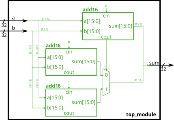
我们将电路分为两段,每段实现16bit的加法,为了使高16位与低16位同时进行运算,我们采用两个add16对高位进行计算,区别在于进位位分别为0和1,最终通过低16位加法器的输出进位作为选择控制信号,选择高16位的运算结果。这样,32bit加法器的延时就变为:16t+tmux2 ≈16t,延时降低了接近一倍,这种以空间(增加电路)换时间(提高速度)的做法,在数字电路设计中经常使用。 请创建Verilog模块,实现上图中的电路结构,其中add16不需要用户编写,其声明如下:
1
2
3
module add16 ( input [15 :0 ] a, input [15 :0 ] b, input cin, output [15 :0 ] sum, output cout );assign {cout,sum} = a + b + cin;endmodule
输入格式
32bit a, 32bit b
输出格式
32bit sum 为 a 与 b 的和
代码和解析
这题和前面几题差不多,没有什么难度,但是这个题介绍的方法很有趣。
1
2
3
4
5
6
7
8
9
10
11
12
13
14
15
16
17
18
19
20
21
22
23
24
25
26
27
28
29
30
31
32
33
34
35
36
37
38
module add16 ( input [15 :0 ] a, input [15 :0 ] b, input cin, output [15 :0 ] sum, output cout assign {cout,sum} = a + b + cin;endmodule module top_module(input [31 :0 ] a,input [31 :0 ] b,output [31 :0 ] sumwire [15 :0 ] sumH0,sumH1,sumL;wire coutL;.a (a[32 :16 ]),.b (b[32 :16 ]),.cin (0 ),.sum (sumH0).a (a[32 :16 ]),.b (b[32 :16 ]),.cin (1 ),.sum (sumH1).a (a[15 :0 ]),.b (b[15 :0 ]),.cin (0 ),.sum (sumL),.cout (coutL)assign sum=(coutL?{sumH1,sumL}:{sumH0,sumL});endmodule
加法减法器
题目描述
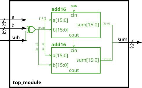
通过对加法器进行改造,可以支持加、减两种运算。我们知道,电路中有符号数通常使用补码表示,如\(-b\) 其补码为:\(\sim b + 1\) (按位取反然后加1)。因此,对于减法算式\(a-b\) ,可以理解为\(a+(-b) = a+(\sim b+1)= a + (\sim b) +1\) ,因此对于减法运算,可以将加法器进行如下改造实现
实现减法运算时,首先通过32bit的异或门,将信号b按位取反,同时将输入进位位置1,实现加法运算时,b保持不变,输入进位位置0。 其中add16模块代码如下,用户可直接调用:
1
2
3
module add16 ( input [15 :0 ] a, input [15 :0 ] b, input cin, output [15 :0 ] sum, output cout );assign {cout,sum} = a + b + cin;endmodule
请创建Verilog模块,实现上述电路功能。
输入格式
32位的a,b,以及一个1位信号sub,sub为1时为减法,sub为0时为加法
输出格式
32位信号sum 注:我想你读到这里的时候,一定跟我一样想着直接用sum=(sub==0?a+b:a-b)逃课了,但是请老老实实地按题目要求分高位低位取补码相加哦~~~
代码与解析
我们先对\(b\) 进行一个处理。如果题目要求加,即sub==0,那么不需要做任何处理,直接加即可。但是如果题目要求减,即sub==1,那么需要求取b的反码,即~b。我们很容易想到,异或可以完成这个工作:遇到0不变,遇到1取反。所以我们可以直接把b和sub异或。
由于减法是\(a+(-b) = a+(\sim b+1)= a + (\sim b) +1\) ,为了实现这个加一,我们直接把sub信号接到第一个全加器的cin上即可。
1
2
3
4
5
6
7
8
9
10
11
12
13
14
15
16
17
18
19
20
21
22
23
24
25
26
27
28
module add16 ( input [15 :0 ] a, input [15 :0 ] b, input cin, output [15 :0 ] sum, output cout );assign {cout,sum} = a + b + cin;endmodule module top_module(input [31 :0 ] a,input [31 :0 ] b,input sub,output [31 :0 ] sumwire [31 :0 ] bXorSub;wire [15 :0 ] sum1,sum2;wire w1;assign bXorSub = b ^ {32 {sub}};.a (a[15 :0 ]),.b (bXorSub[15 :0 ]),.cin (sub),.sum (sum1),.cout (w1).a (a[31 :16 ]),.b (bXorSub[31 :16 ]),.cin (w1),.sum (sum2)assign sum={sum2,sum1};endmodule
always过程块_组合逻辑
题目描述
所有的数字电路都是由逻辑门和连线构成的,因此理论上来说都可以通过模块的连接和assign语句进行描述,然而在很多情况下这并不是最方便的一种方式,过程块提供了一种更加方便的描述方式,always过程块便是其中最常用的一种。 对于可综合电路(即能转化成实际电路的verilog描述方式,与之相对的是不可综合电路,多用于电路仿真,不能转换成实际电路),有两种always块的语法形式:
组合逻辑电路:always@(*)
时序逻辑电路:always@(posedge clk)
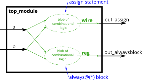
组合逻辑电路的always块与assign语句等效,用户描述组合逻辑电路时,可根据便利性选择其中一种方式使用。两者生成的硬件电路一般是等效的,但在语法规则上稍有不同:
assign语句只能对一个信号进行赋值,always块内可对多个信号进行赋值assign语句中被赋值信号为wire类型,always块内被赋值信号需定义为reg类型always块内支持更加丰富的语法,如使用if…else..、case等适合实现交复杂的组合逻辑 例如下述两条语句是等效的(out1需定义为wire类型,out2需定义为reg类型,但这仅仅是语法上的要求,生成的电路并没有区别): 1 2 assign out1 = a & b | c ^ d;always @(*) out2 = a & b | c ^ d;
always语句后的括号内放的是敏感变量列表,对于上例来说,可以写成always @(a,b,c,d) out2 = a & b | c ^ d,但为了简单起见,我们一般都用符号*代替。 试创建一verilog模块,实现一与门,分别用assign语句和always块实现。
输入格式
1位的a,1位的b
输出格式
1位的out_assign,1位的out_alwaysblock
代码和解析
这道题向我们介绍了一个叫做“过程块”的事物,它就是always。在过程块中被赋值的变量必须是reg类型,尽管综合时可能和平常所使用的assign得到的电路没有区别。
1 2 3 4 5 6 7 8 9 10 11 module top_module(input a, input b,output wire out_assign,output reg out_alwaysblockassign out_assign = a & b;always @(*) begin end endmodule
always过程块_时序逻辑
题目描述
通过前例已经了解到,对于可综合电路,有两种always块的语法形式:
组合逻辑电路:always@(*)
时序逻辑电路:always@(posedge clk)
用always描述的时序逻辑电路,除了像组合逻辑always块那样生成组合逻辑电路外,还会生成一组触发器(或称寄存器),用于寄存组合逻辑的输出。寄存器的输出只有在时钟的上升沿时(posedge clk)才会更新,其余时刻均保持不变。 阻塞赋值和非阻塞赋值: 在Verilog中,有三种赋值方式,分别为:
连续赋值(如assign x = y;),该赋值方式只能用于过程块(如always块)之外
阻塞赋值(如x = y;),该赋值方式只能用在过程块(如always@(*))内
非阻塞赋值(如x <= y;),该赋值方式只能用在过程块内(如always@(posedge clk))
在设计Verilog模块时,请遵循以下原则:
在组合逻辑的always块内采用阻塞赋值
时序逻辑的always块内采用非阻塞赋值
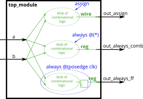
违背这一原则将可能导致难以发现的电路错误,且可能导致仿真与综合的不一致,请用户切记。至于为何这样,初学者可以不必理会,简单理解为verilog语法规范性要求即可。 创建一verilog电路,分别采用上述三种赋值方式实现异或门电路,如下图所示:
Hint
always块内被赋值的信号都应定义成reg类型
always块内,组合逻辑采用阻塞赋值(a = b),时序逻辑采用非阻塞赋值(a <= b)
always语句括号内是敏感变量列表,时序逻辑是边沿敏感的,posedge clk表示的是clk信号的上升沿,此外,还可以是negedge clk,表示clk信号的下降沿。
输入格式
一位线网型变量clk,a, b。clk为时钟,a,b为输入
输出格式
一位线网型变量out_assign,out_always_comb,out_always_ff。out_assign为a,b连续赋值得到的结果。out_always_comb为a,b阻塞赋值得到的结果。out_always_ff为a,b非阻塞赋值得到的结果
代码和解析
连续性赋值总是处于激活状态,任何操作数的改变都会影响表达式的结果;过程赋值只有在语句执行的时候,才会起作用。这是连续性赋值与过程性赋值的区别。
阻塞赋值属于顺序执行,即下一条语句执行前,当前语句一定会执行完毕。例如:
1 2 3 4 5 6 7 8 9 wire sel, a, b ;reg y , c ;always @( sel or a or b ) begin if ( sel == 1'b1 ) begin end else y = b ;end
这就是阻塞赋值,先执行c=a,再执行y=c,这段代码等价于:
1 2 wire sel, a, b, y ;assign y = ( sel == 1 ’b1 ) ? a : b ;
非阻塞赋值属于并行执行语句,即下一条语句的执行和当前语句的执行是同时进行的,它不会阻塞位于同一个语句块中后面语句的执行。例如:
1 2 3 4 5 6 7 8 9 10 11 12 13 module Cyclic_shifter ( clk, rst_n, Q );input clk, rst_n ;output [ 2 : 0 ] Q ;reg [ 2 : 0 ] Q ;always @ ( posedge clk or negedge rst_n ) begin if ( ~rst_n ) Q <= 3'b001 ;else begin 0 ] <= Q[2 ] ; 1 ] <= Q[0 ] ; 2 ] <= Q[1 ] ; end end endmodule
非阻塞赋值是先计算出要“赋”的“值”,然后到块结束再统一“赋予”。例如上面的代码,就是利用非阻塞赋值来交换了三个变量的值。
本题的代码为:
1 2 3 4 5 6 7 8 9 10 11 12 13 14 15 16 17 18 module top_module(input clk,input a,input b,output wire out_assign,output reg out_always_comb,output reg out_always_ff assign out_assign = a ^ b;always @(*) begin end always @(posedge clk) begin end endmodule
if…else…语句
题目描述
if语句用于过程块内部,其对应的电路是二选一的选择器,
以下述代码为例:
1 2 3 4 5 always @(*)begin if (condition) out = x;else out = y;end
上述代码与下面的assign语句完全等效:
1 assign out = (condition) ? x : y;
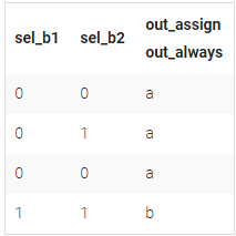
试创建一Verilog模块,分别采用assing语句和过程块内的if语句实现下述选择器电路:
Hint: 1. if…else…可以嵌套使用
使用if语句描述组合逻辑时,务必加上else语句,以免产生锁存器(数字电路设计中应尽力避免产生锁存器)
本题两个输出信号波形其实是完全一致的,原则上是为了训练大家采用assign和过程块内的if语句使用,所以希望大家能够两种方式都各自尝试一下
输入格式
信号a, b, 选择信号sel_b1, sel_b2
输出格式
通过assign语句选择的信号out_assign 通过if语句选择的信号out_always
代码和解析
1 2 3 4 5 6 7 8 9 10 11 12 13 14 15 16 17 module top_module(input a,input b,input sel_b1,input sel_b2,output wire out_assign,output reg out_always); assign out_assign = (sel_b1 & sel_b2) ? b : a;always @(*) begin if (sel_b1 & sel_b2)else end endmodule
本站的运行成本约为每个月5元人民币,如果您觉得本站有用,欢迎打赏:
