[toc]
准备工作
安装Vivado软件,VSCode软件,VSCode的Verilog插件
在环境变量中加入Vivado的XVlog,以便VSCode检查
在Vivado中新建一个project,除取名和选择路径以外一路Next即可。
来到了以下界面
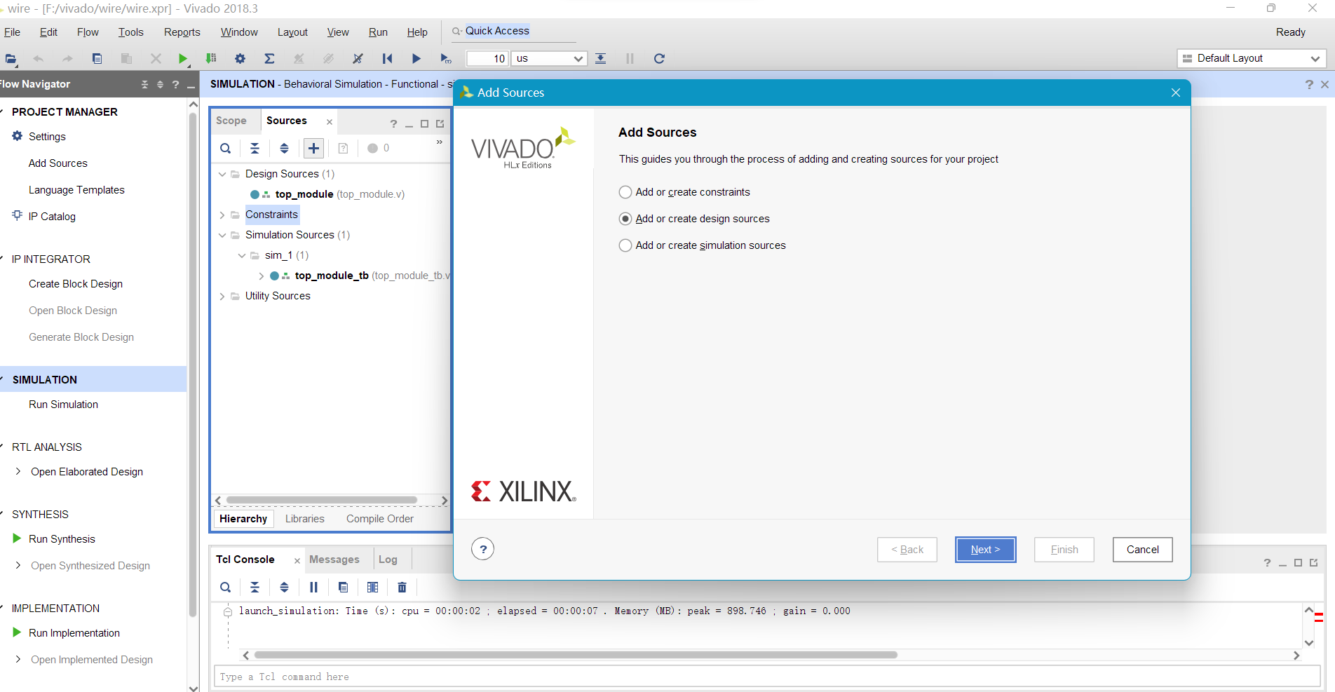 image-20221008230354388
鼠标选择Constraints,点加号,在弹出的窗口中选择第二个选项,点Next,点Creat
File新建一个文件,文件名最好是模块名。
点小齿轮(设置),点Text Editor,选择Custom
Editor,输入.../Microsoft VS Code/Code.exe -g [file name],点OK
先打开VSCode软件,再双击Vivado Sources/Design
Sources里你刚刚新建的.v文件,弹出新VSCode窗口,于是可以开始写代码了。
输出1
题目描述
编写 Verilog 代码,使电路输出信号1
输入格式
无输入
输出格式
输出1,位宽为1
代码和解析
1
2
3
4
| module top_module(out);
output wire out;
assign out = 1'b1;
endmodule
|
这个题没什么好解析的,直接用assign赋值即可,主要熟悉基本的操作。Verilog的基本结构是模块,也就是这里面的module,一个模块代表一个功能单元。模块最基本的结构是这样的:
1
2
3
4
5
| module 模块名称(端口列表);
input 数据类型(reg 或 wire) 输入端口表;
output 数据类型(reg 或 wire) 输出端口表;
endmodule
|
上述的声明方法是Verilog-1995标准 风格,还有一种声明方法是这样的:
1
2
3
4
5
| module 模块名 #(参数声明1,参数声明2,...)
(端口声明 端口1,端口2,...,
端口声明 端口3,端口4,....);
endmodule
|
以这种风格书写的本题代码是这样的:
1
2
3
4
5
| module top_module(
output out
);
assign out = 1'b1;
endmodule
|
输出0
把上题中的1变成0即可,略。
wire
题目描述
wire 是 Verilog 的关键字,用于表征信号类型的,其含义是线网。wire
可理解为物理连线,但又有所不同,因为 Verilog 中的 wire
是有方向的。例如设计一模块,模块名命名为 top_module,输入信号名为
in,输出信号名为 out,使 in 与 out 直连,如下图所示:
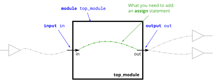
请使用 assign 语句将代码补充完整,使其实现上述电路图的功能。
输入格式
任意
输出格式
与输入完全相同
代码和解析
Verilog的变量有两种最基本的类型,即wire和reg,默认1位宽。
wire如其名字所示,表示连线。驱动端信号的改变会立刻传递到输出的连线上。输入输出端口,如果不另行声明类型,都默认为`wire,如果使用assign的连续赋值语句,被赋值的变量都得是wire。
reg的意思是寄存器,它能保持其值,直到它被赋于新的值。在行为建模中,在过程块(always块)中被赋值的变量必须是reg类型
还有其它类型,如整数、实数、比特矢量、数组,等用到了再说。
这个题的代码实现是:
1
2
3
4
5
| module top_module(in,out);
input wire in;
output wire out;
assign out = in;
endmodule
|
多个端口的模块
题目描述
wire是Verilog的关键字,用于表征信号类型的,其含义是线网,wire可理解为物理连线,但又有所不同,因为verilog中的wire是有方向的,例如设计一模块,模块名命名为top_module,输入信号名为in,输出信号名为out,使in与out直连,如下图所示:
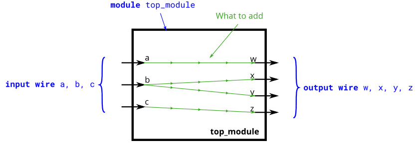
请使用assign语句将代码补充完整,使其实现上述电路图的功能
输入格式
1 1 1
输出格式
1 1 1 1
代码和解析
这题没啥解析的,和上一题差不多。
1
2
3
4
5
6
7
8
9
| module top_module(a,b,c,w,x,y,z);
input wire a,b,c;
output wire w,x,y,z;
assign w=a;
assign x=b;
assign y=b;
assign z=c;
endmodule
|
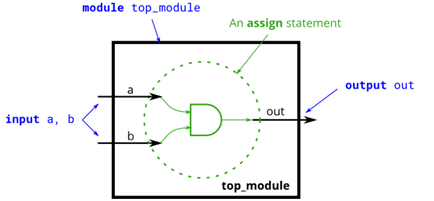
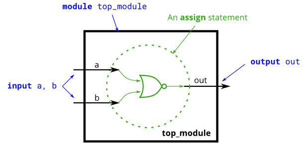
非门
题目描述
创建一个名为top_module的Verilog模块,实现非门的功能
输入格式
无
输出格式
无
代码和解析
在这个题里,我们要介绍一下连续赋值。总的来说,Verilog里有两种赋值,叫做过程赋值和连续赋值。其中过程赋值主要在initial或always块中使用,我们也是到时候再说,先来说连续赋值。
连续赋值的格式是:
其中被赋值量只能是wire型的,值的类型没有限制。
本题的代码为:
1
2
3
4
5
| module top_module(a,b);
input wire a;
output wire b;
assign b = ~a;
endmodule
|
与门
和上一题差别不大
1
2
3
4
5
| module top_module(a,b,out);
input wire a,b;
output wire out;
assign out=a&b;
endmodule
|
或非门
和上一题的差别不大,或非的意思就是先或再非。
1
2
3
4
5
| module top_module(a,b,out);
input wire a,b;
output wire out;
assign out=~(a|b);
endmodule
|
同或门
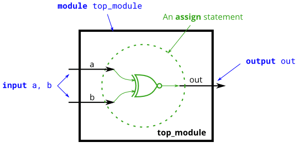
和上一题差别不大,同或的意思就是俩信号一样就是0,不一样就是1,也就是异或取反。
1
2
3
4
5
| module top_module(a,b,out);
input wire a,b;
output wire out;
assign out=~(a^b);
endmodule
|
线网型中间信号
题目描述
之前的verilog模块结构都比较简单,输出信号可直接用输入信号的逻辑表达式表示出来,模块功能稍微复杂时,一般都会用到中间信号,以下图为例,输入信号in经过两个非门后输出到out端口,为了在verilog模块中表示两个非门中间的这跟信号,需要将其定义为线网型(wire)信号,此处我们命名为not_in。
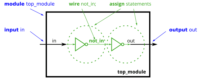
上述模块的verilog代码为:
1
2
3
4
5
6
7
8
9
| module top_module (
input in,
output out;
);
wire not_in;
assign out=~not_in;
assign not_in=~in;
endmodule
|
请根据上述示例,完成下图中电路所对应的Verilog模块
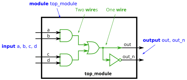
输入格式
四个线网型变量a、b、c、d
输出格式
两个线网型变量out、out_n
代码和解析
这个题属于稍微复杂一点的组合逻辑,需要用到中间变量。在做题以前,我们先观察一下他给我们的代码,里面有这么两句:
1
2
| assign out=~not_in;
assign not_in=~in;
|
有同学可能就问了,按照逻辑,难道不应该是not_in先有值,然后out才有值吗?怎么能先给out赋值呢?这就是Verilog的一个特点,那就是并行赋值。你不要把这两个语句当成C语言,先执行上面的,再执行下面的,而是要当成图里面那个电路,输入信号来的时候,not_in和out有先后之分吗?忽略光速和元件延时的情况下,显然没有。
根据给出的图,我们很容易写出下面的代码:
1
2
3
4
5
6
7
8
9
| module top_module(a,b,c,d,out,out_n);
input wire a,b,c,d;
output wire out,out_n;
wire x,y;
assign x = (a&b);
assign y = (c&d);
assign out = x|y;
assign out_n=~(x|y);
endmodule
|
但是有个问题,就是我们不知道这个代码对不对。那么怎么知道我们的代码是怎么运行起来呢?在C语言里,我们一般是编译执行然后在控制台里输入一些数据,看输出是不是符合我们的期待。在Verilog中,我们也要给程序输入一些信号,看输出的信号是否符合我们的期待,但是这个过程比C语言的要复杂一些:我们还要再写一个Verilog代码,它叫做“testbench”。
首先我们回到Vivado软件,鼠标选择Constraints,点加号,在弹出的窗口中选择第三个选项,点Next,点Creat
File新建一个文件,文件名最好是“模块名_tb”。这里的“tb”就是"testbench"的意思。然后,在Simulation
Source里面就生产力testbench代码。
testbench代码的基本结构是这样的:
1
2
3
4
5
6
7
8
9
10
11
12
13
14
15
16
| `timescale 1ns / 1ps
module 模块名_tb;
reg 输入端口名1,输入端口名2,...;
wire 输出端口名1,输出端口名2,...;
模块名 模块的示例名(.端口名1(端口1),.端口名2(端口2),...);
initial begin
输入端口1=值1_1;输入端口2=值1_2;...
#50;
输入端口1=值2_1;输入端口2=值2_2;...
#50;
...
输入端口1=值n_1;输入端口2=值n_2;...
#50;
$stop;
end
endmodule
|
这里面有几个我们之前没见过的东西。首先是第一行
这个以反撇号开头的语句叫做编译指令,用于说明参考时间单位和仿真时间精度。
然后是第五行
1
| 模块名 模块的示例名(.端口名1(端口1),.端口名2(端口2),...);
|
这个叫做“例化”,可以类比C语言里面的“调用”。在C语言中,调用一个函数只能按顺序传参,但是在Verilog里,可以像这里一样端口命名法传递信号。
然后是第十行
这个的意思是延时50个时间单位。
于是,我们可以写出这道题的testbench代码:
1
2
3
4
5
6
7
8
9
10
11
12
13
14
15
16
17
18
19
20
21
22
23
24
25
26
27
28
29
30
31
32
33
34
35
36
37
38
39
40
41
| `timescale 1ns / 1ps
module top_module_tb;
reg a, b, c, d;
wire out, out_n;
top_module ul(.a(a),.b(b),.c(c),.d(d),.out(out),.out_n(out_n));
initial begin
a=0;b=0;c=0;d=0;
#50;
d=1;c=0;b=0;a=0;
#50;
d=0;c=1;b=0;a=0;
#50;
d=1;c=1;b=0;a=0;
#50;
d=0;c=0;b=1;a=0;
#50;
d=1;c=0;b=1;a=0;
#50;
d=0;c=1;b=1;a=0;
#50;
d=1;c=1;b=1;a=0;
#50;
d=0;c=0;b=0;a=1;
#50;
d=1;c=0;b=0;a=1;
#50;
d=0;c=1;b=0;a=1;
#50;
d=1;c=1;b=0;a=1;
#50;
d=0;c=0;b=1;a=1;
#50;
d=1;c=0;b=1;a=1;
#50;
d=0;c=1;b=1;a=1;
#50;
d=1;c=1;b=1;a=1;
#50;
$stop;
end
endmodule
|
呃,说实话,这个代码不是我写的,是我写的代码帮我写的。
1
2
3
4
5
6
7
8
9
10
11
12
13
14
15
16
17
18
19
20
21
22
23
24
25
26
27
28
29
30
31
32
33
34
35
36
37
38
39
40
41
42
43
44
45
46
47
48
49
50
51
52
53
54
55
56
57
58
59
60
61
62
63
64
65
66
67
68
69
70
71
72
73
74
75
76
| #include <cstdio>
#include <iostream>
const double eps = 1e-11;
using namespace std;
int main() {
printf("输入模块名称:");
char s[100];
scanf("%s", s);
printf("输入input信号个数:");
int NumInput;
scanf("%d", &NumInput);
printf("依次输入input信号名称:");
string inputSign[100];
for (int i = 1; i <= NumInput; ++i) {
cin >> inputSign[i];
}
printf("输入output信号个数:");
int NumOutput;
scanf("%d", &NumOutput);
printf("依次输入output信号名称:");
string outputSign[100];
for (int i = 1; i <= NumOutput; ++i) {
cin >> outputSign[i];
}
cout << "`timescale 1ns / 1ps\n";
cout << "module " << s << "_tb;\n";
cout << " reg ";
for (int i = 1; i <= NumInput; ++i){
cout << inputSign[i];
if(i!=NumInput) cout<<", ";
}
cout << ";" << endl;
cout << " wire ";
for (int i = 1; i <= NumOutput; ++i){
cout << outputSign[i];
if(i!=NumOutput) cout<<", ";
}
cout << ";" << endl;
cout << " " << s << " ul(";
for (int i = 1; i <= NumInput; ++i)
cout << "." << inputSign[i] << "(" << inputSign[i] << "),";
for (int i = 1; i <= NumOutput; ++i) {
cout << "." << outputSign[i] << "(" << outputSign[i] << ")";
if (i != NumOutput) cout << ",";
}
cout << ");" << endl;
cout << " initial begin" << endl;
int pow2in = 1 << NumInput;
for (int i = 0; i <= pow2in-1; ++i) {
cout<<" ";
int temp = i, cnt = NumInput;
if (i == 0) {
for (int j = 1; j <= NumInput; ++j)
cout << inputSign[j] << "=0;";
} else {
while (temp && cnt>=1) {
cout << inputSign[cnt] << "=" << temp % 2 << ";";
temp = temp / 2;
--cnt;
}
if(cnt>=1){
for(int j=cnt;j>=1;--j){
cout << inputSign[j] << "=0;";
}
}
}
cout <<endl<< " #50;"<<endl;
}
cout << " $stop;"<<endl;
cout << " end" << endl;
cout << "endmodule" << endl;
return 0;
}
|
保存文件,点这个
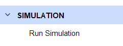 image-20221009000446371
Vivado就产生了对应的波形:
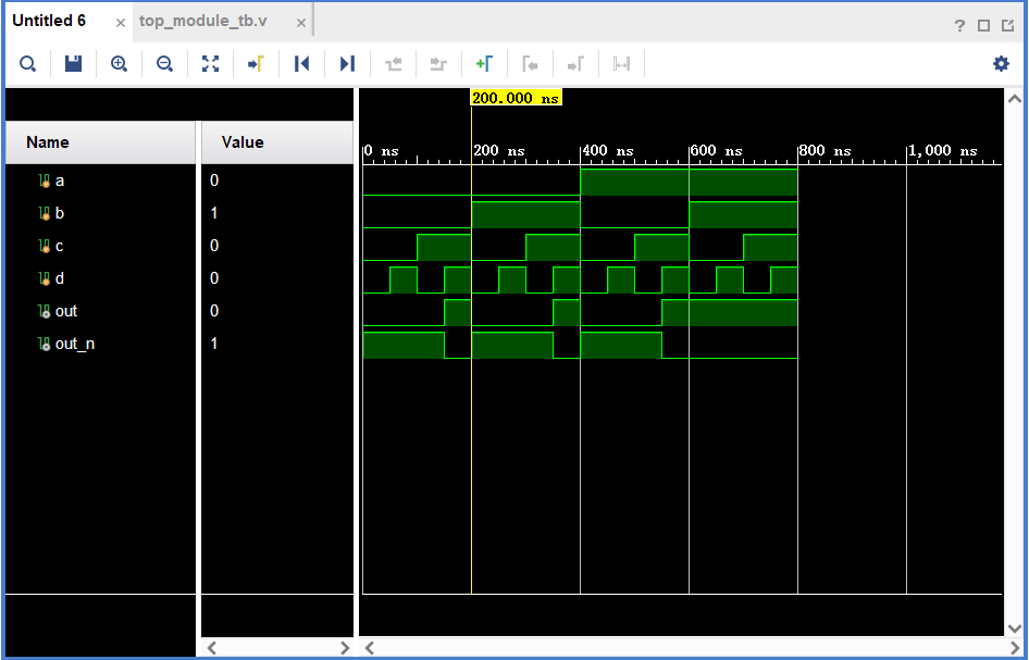 image-20221009000506234
我们就能照着这个看自己写的对不对了。
本站的运行成本约为每个月5元人民币,如果您觉得本站有用,欢迎打赏: